EN


The shielding box needs to be well shielded, and the most ideal state seems to be "without holes". However, in actual testing, according to the power supply, data communication, network connection, or RF signal transmission requirements of the tested product (DUT), corresponding interfaces such as USB, Type-C, RJ45, AC, BNC, etc. need to be selected to establish connections with external devices. Therefore, the design of the shielding box needs to address two issues simultaneously: maintaining the continuity of the shielding structure, isolating external electromagnetic interference, and ensuring the normal transmission of necessary power, data, and RF signals. How to strike a balance between "isolation" and "conduction" has become the key to the design of shielding box interfaces.
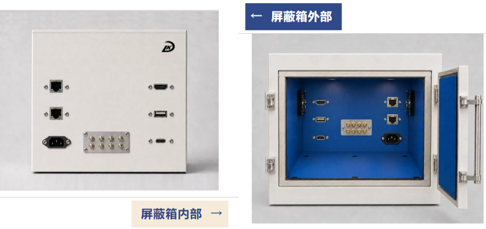
Interfaces are not simply 'holes'
The interface is a necessary channel for connecting signals inside and outside the shielding box, and it is also a key location that affects shielding performance. When designing, it is necessary to consider signal conduction, filtering, and grounding, while ensuring normal transmission and reducing electromagnetic interference.
Different interfaces correspond to different design priorities
USB/Type-C is commonly used for testing consumer electronics and IoT devices, providing power supply, debugging communication, and device control functions. High speed digital cables are prone to coupling with spatial electromagnetic interference, and their own digital pulse noise can also leak out. Therefore, this type of interface needs to be equipped with a dedicated filtering component, combined with a fully shielded structure and standardized grounding, to block interference from conducting bidirectionally along the cable while ensuring transmission rate and power supply, and to avoid digital noise pollution in the RF testing environment.
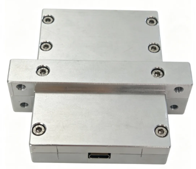
Type-C filter connector
The RJ45 network port is mainly responsible for network communication functions and is commonly used for testing equipment networking, data uploading, and automation control. A regular Ethernet cable passing through the box will directly connect the electrical circuits inside and outside the box. External high-frequency interference can enter the cavity along the Ethernet cable, and the RF signal inside the box will also leak outward. It is necessary to match the filtering network and shielded connector based on the transmission bandwidth and test frequency band to achieve smooth network links while attenuating conducted electromagnetic interference.
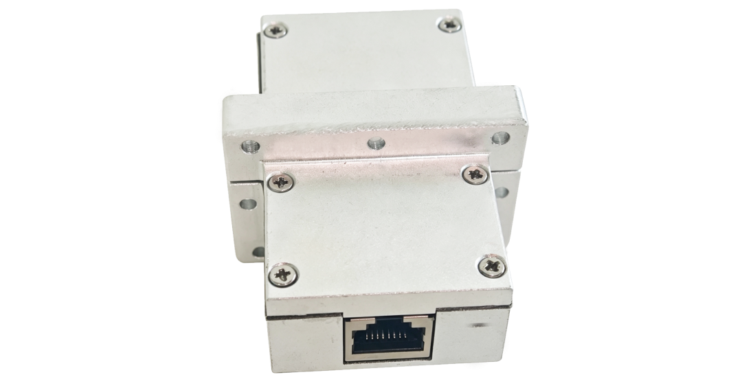
RJ45 filter connector
The AC power input port supplies power to the tested machine and its internal components. Although it appears to have a simple structure, it is the main entrance for conducting interference. The municipal power grid is mixed with a large amount of harmonic and pulse interference. When there is no isolation design for ordinary power interfaces, the power grid noise will enter the shielding cavity along the power lines. High standard testing scenarios will integrate power filtering modules, allowing only power frequency electricity to pass through and filtering out various high-frequency electromagnetic clutter.
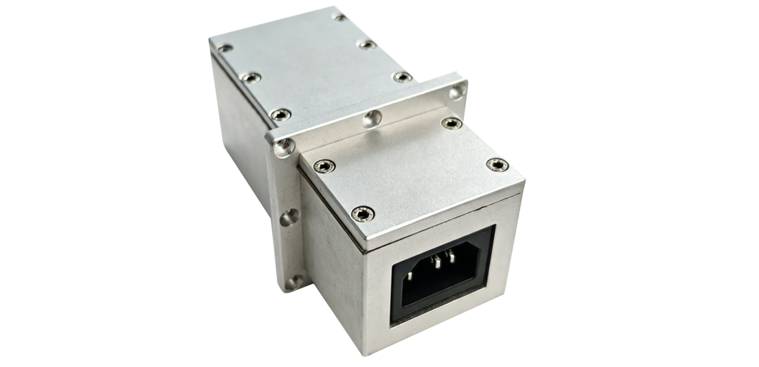
[Physical picture of AC filtering interface]
BNC coaxial RF interface is different from power and data interfaces. BNC itself is used for directional transmission of RF test signals, and has more stringent requirements for shielding and control. RF testing requires precise and controllable input signals, and must avoid environmental stray interference from entering the testing link. BNC relies on coaxial shielding structure, flange sealed installation, and cavity common ground design to define a unique and standardized RF transmission path; Compared to random drilling and threading, it can eliminate signal loss, electromagnetic crosstalk, and reduced shielding effectiveness of the cavity, ensuring the accuracy of RF testing.
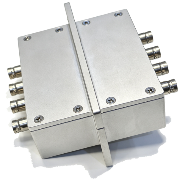
BNC filter connector
The more interfaces there are, the higher the difficulty of shielding design
An increase in the number of interfaces does not necessarily mean a decrease in shielding performance, but it will significantly increase the overall design difficulty. On the one hand, with each additional interface, a new shielding boundary is added, which requires separate handling of drilling, installation, grounding, and filtering issues. On the other hand, the signal characteristics corresponding to different interfaces are not the same. There are differences in filtering methods, circuit layouts, and connection structures among power supplies, high-speed digital signals, network signals, and RF signals.
When multiple interfaces are concentrated on the same shielding box, further consideration is needed for interface spacing, internal wiring, grounding paths, filter installation space, and the mutual influence between different signals. Therefore, the multi interface shielding box is not simply a combination of multiple standard connectors, but requires comprehensive design from the perspective of the overall testing system.
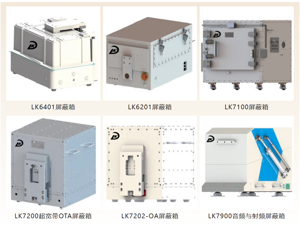
>Customized shielding box/filter
Liankang Information can provide customized shielding box and filter connector services for different DUTs, testing frequency bands, and testing system requirements. According to actual application requirements, targeted design can be carried out for the size, structural form, interface type, interface quantity, installation position, and filtering scheme of the box, and multiple interface configurations such as USB, Type-C, RJ45, AC, BNC, etc. are supported. From interface requirements to overall structure, through the collaborative design of shielding, filtering, and connection schemes, the stability and reliability of the testing environment are taken into account while meeting the signal conduction requirements.
 Tel:173 9470 0835
 E-mail:support@lk-tek.com
 Add:No. 246 Wencheng East Road, Siyang County Economic Development Zone, Suqian City, Jiangsu Province